EN 13524[1]EN 13524:2003+A2:2014 Highway maintenance machines. Safety requirements, Polish edition PN-EN 13524+A2.2014 Maszyny do utrzymania dróg. Wymagania bezpieczeństwa introduces some safety requirements for highway mowers, e.g. deflection bars.
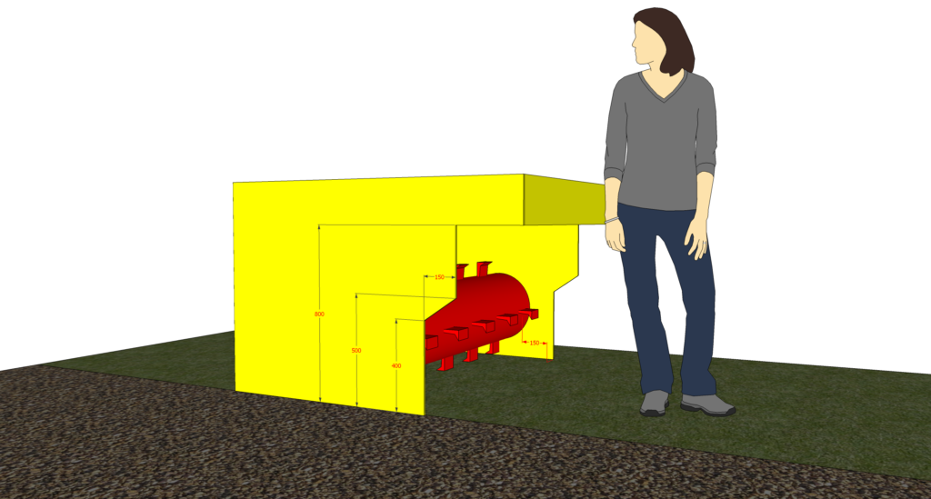
a) Guard on mowing and mulching machines in the direction of feeding and ejecting
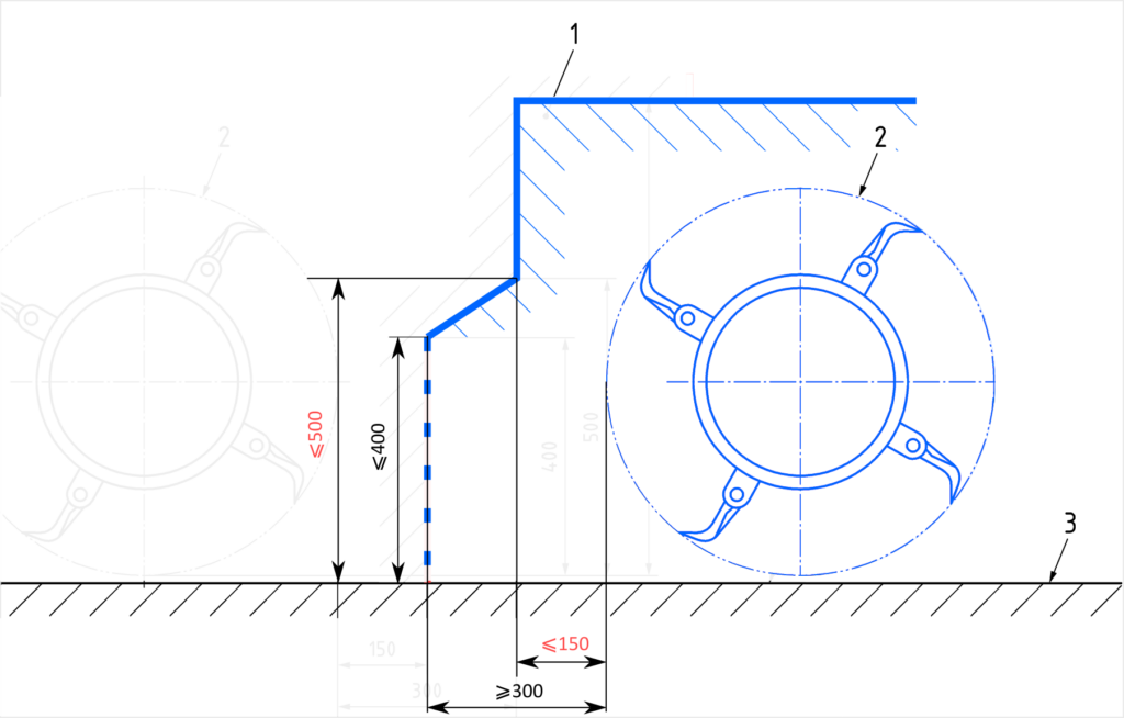
Guards in the direction of feeding and ejecting, e.g. deflector bar, shall be arranged as shown in Figure 1. The spacing shall be measured from the path of rotation of the tools, where the mulching or mowing machine is in the operating position.
EN 13524 / 5.17 Special protection measures to prevent unintentional contact with revolving tools in the operating area of mowing and mulching machines
The requirement is illustrated with the mentioned Figure 1:

Figure 1 — Mowing machine with a horizontal axis in the operating position – Protection by means of deflector bar
Contradictions
1. Item 1 is an “area within the guard”. If so, the guard itself is the neighbouring polyline, having the interior on the right side of the picture. Thus, the rotating element (on the left) is outside the guard. (!)

2. The hatching is, however, on the left side of the supposed guard. Hatching is used in cross-sectional views to show where a solid material is, like on the picture below:

In the case of Figure 1 it would mean, that the polyline shows the inner surface of the guard. The item 1 would be inside the guard (as described), and the guard itself would be made of a very, very thick piece of metal (or so), extending infinitely to the left, with the rotor… sunk into this metal (or so) piece. (!)

3. Or the cross section could be made in the plane of the guard side cover. In this case the polyline would determine the side cover shape.

Other errors
4. It should be noticed, that the hatching of the guard is same as that of the ground. It was different for the two objects in previous standard release (EN 13524:2003), so it is unified on purpose. The same hatching means the same object. Moreover, there is no gap between the guard and the ground. Did the authors have trenches in mind?
5. The values given, are they minimum or maximum?
Proposal
1. Comparing the polyline with actual machines, it would make sense reversed from left to right (or move the rotor to the other side of the picture).

2. The lowest part of the polyline (mark as dash line) stands for an opening. The standard should precise, that the opening should be covered with means like rubber or chains.
3. The top-most part of the polyline (vertical segment above the 800) is irrelevant (has no impact on safety) and should be removed.
4. The guard height (800) is irrelevant and should be removed.
5. The values 500 and 150 (marked red) seem irrelevant and should be removed.
6. The opening height (400) is maximum and the distance from rotor (300) is minimum.
7. 400 mm as opening height seems much too big and decrease should be considered.

